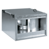
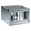
Blauberg Box-I


- Description
- Modifications
- Capacity diagram
- Downloads
- Designation key
- Accessories
| USE |  |
|
Supply and exhaust ventilation systems installed in various premises.Compatible with 400x200 up to 600x350 mm rectangular air ducts. |
|
| DESIGN | |
|
Atmospheric resistant galvanized steel casing and impeller.The casing is heat- and sound-insulated with 50 mm mineral wool.The fan is rated for continuous operation.Fitted with standard 20 mm connecting flanges for connection to rectangular air ducts.Access cover on the casing for inspection and maintenance operations.The fan is equipped with a built-in terminal box with a leaded outside sealed electrical lead-in for connection to power mains. |
|
| MOTOR | MOUNTING |
|
Two- or four-pole asynchronous motor with external rotor and centrifugal impeller with backward curved blades.Single-phase (E) or three-phase (D) motor modifications.Equipped with ball bearings for longer service life.Dynamically balanced impeller.Overheating protection by built-in thermal switches with automatic restart or with leaded outside terminals for connection to external protecting controls.The thermal switch terminal leads are designed for connection to respective circuit of the contacter, overload relay or respective terminals of the autotransformer or thyristor speed controller. |
The fan is designed for mounting inside rectangular air ducts and can be installed in any position.The fan flanges are connected to the air ducts through the bolts inserted into the flange holes.The fan is suitable for mounting into round duct at intake flange with a round reducer (available upon separate order).If vibration-absorbing flexible connectors are used to connect the fan to the air ducts provide their fixation to mounting structures with supports or brackets.While mounting provide enough space for accessing the cover for service operations. |
| SPEED CONTROL | |
|
Smooth speed control with an external thyristor controller or step speed control with an external auto transformer (both available upon separate order). |
| Modification name |
|---|
| Box-I 40x20 2E |
| Box-I 50x25 2E |
| Box-I 50x30 4D |
| Box-I 50x30 4E |
| Box-I 60x30 4D |
| Box-I 60x30 4E |
| Box-I 60x35 4D |
| Box-I 60x35 4E |
| Modification name | |
|---|---|
| Box-I 40x20 2E | |
| Box-I 50x25 2E | |
| Box-I 50x30 4D | |
| Box-I 50x30 4E | |
| Box-I 60x30 4D | |
| Box-I 60x30 4E | |
| Box-I 60x35 4D | |
| Box-I 60x35 4E |
|
|
|
|
|
|
|
|
|
|
|
|
|
|
|
|
- Selection method:
- Air capacity:
- Pressure:
- Air capacity: --
- Pressure: ---
| Series | Flange size (width x height) [cm] | Motor Number of poles |
Phase |
| Box-I | 40x20; 50x25; 50x30; 60x30; 60x35 | 2; 4 |
E: single-phase |

 Domestic fans
 Industrial fans
 Single-room air handling units with heat recovery
 Air handling units
  Smoke extraction and ventilation
 Ventilation accessories
 Ventilation ducts and fittings
 Air distribution
 Measurement and control technology
 Ventilation sets and vents


